This software can be operated within two subsystems:
- Monitoring and diagnostics subsystem (server-installed);
- Outdoor illumination operation modes control subsystem (installed at the dispatcher’s automated workstation).
The monitoring and diagnostics subsystem contains:
- Database management system (DBMS) on the server with a static IP address for access to the Internet;
- Software (SW) for monitoring and diagnostics which ensures automatic collection of process parameters in specified time interval from all lighting control cabinets (LCCs), including results of diagnostics of lighting fixtures (LF) diagnostics operating in the illumination system and transmission of data DBMS for storage.
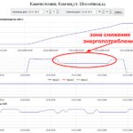
The DBMS contains both numeric values of parameters arranged in tables, and the graphic representations of their time characteristics (currents, voltages, consumed power, etc.).
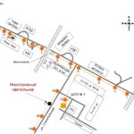
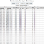
Faulty LFs are identified at the end of each operating cycle of the lighting network and are marked with black dots on the graphic logic board of the lighting line, indicating the numbers of faulty LFs. The number of these is also reflected in the table of results of process parameters monitoring.
The results of the process parameters monitoring on the server can be viewed by an authorized user via a local computer network or remotely via Internet from a stationary PC or from a mobile device (smartphone, tablet PC, laptop) around the clock.
It is possible to remotely export data from the server DBMS for further processing and analytical reporting.
Note: The software can either be purchased separately or as a part of a server cabinet. It is possible to use the monitoring and diagnostics OIACS subsystem as a cloud: this option must be specified at concluding the contract for information support and maintenance of the OIACS.
The screens demonstrating the operation of the monitoring and diagnostics subsystem are shown in the figures below.
The control subsystem includes three SW levels:
- Lower level — power supply network control (PNSCR) receiver software.
It allows to set (change) individual (from 1 to 220) and group (from 1 to 29) addresses of PNSCR by means of PNSCR programmer unit, choose the scene number for PNSCR (from 1 to 20), and, correspondingly, for the lighting fixture, to change PWM parameters (frequency, inversion, etc.), and other parameters. In addition, the PNSCR software implements acceptance and transmission algorithms of signals via power network from LCC to LF power source control (driver). This software is recorded into the PNSCR permanent memory. - Middle level — lighting control cabinet (LCC) software.
It ensures address transmission of PNSCR control commands, collection of process information and results of LF diagnostics, its processing, temporary storage and data exchange with diagnostics and control subsystems. This software is stored in the LCC permanent memory.
- Upper level — dispatcher’s AW software.
Ensures remote control of operation modes of the outdoor lighting network, adjust the schedule of lighting control cabinets, perform unscheduled LF diagnostics, implement other functions of the OIACS. This software is installed on a personal computer (PC) or laptop, purchased separately or as a part of the dispatcher’s workstation.
 RUS
RUS ENG
ENG


